Librem 5 Development Kit
Note
If you experience problems with the development kit, you may find it useful to consult the Known Issues page and Troubleshooting guide.
Development Kit Package
The package contains:
- Receipts
- An informational leaflet
- A 5V @ 3A USB power supply with a USB-A (non-SS) socket
- A cable with a USB-A (non-SS) plug on one side and a USB-C plug on the other
- The dev board, composed of the following detachable parts:
- The base board, AKA Librem 5 Dev Kit v1.0.0
- The SIM7100E modem in the Europe version, SIM7100A in the US version, with an antenna cable attached – see here for details
- The EmCraft SoM with a Quad iMX8M
- A camera module marked TRULY-M (covered with a paper protector)
- The RedPine Signals WiFi/BT module with 2 antenna cables attached
The development board accepts the following items, not included in the package:
- a MicroSD card
- a Micro/3FF SIM card (15×12mm)
- a Mini/2FF GPG smart card (25x15mm)
- a protected 18650 Li-ion battery that meets the specs on the silkscreen
- Built-in over-voltage, under-voltage, over-current, and over/under-temperature protection
- minimum cell voltage of 2.5V or less
- maximum cell voltage of 4.2V or more
- maximum discharge current of 8A or more
- maximum charge current of 1.6A or more
Warning
If a battery is used with the board, it must be inserted in the
battery holder instead of being connected indirectly via
adaptors or jumper wires. Use of the battery holder ensures that
thermal regulation can be used as an additional precaution
against overheating.
The polarity marking must be followed when
inserting the battery otherwise there is a risk of damaging the
board and/or the 18650 cell.
Notably, the development board has an Ethernet port, a single USB-C port, and a Mini-HDMI port.
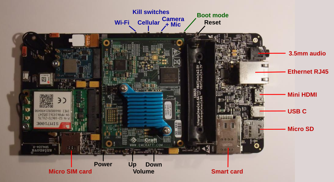
The positions and types of sockets, push buttons and switches (click to enlarge). Ports, right hand side, top to bottom: 3.5mm audio socket, RJ45 Ethernet socket, mini HDMI socket, USB C socket, micro SD card socket. Kill switch side, right to left: reset button, boot mode switch, camera + microphone kill switch, cellular kill switch, Wi-Fi kill switch. Button side, right to left: smart card socket, volume down button, volume up button, power button, micro SIM card socket.
See the hardware_reference for information about the specific parts used for the sockets, buttons and switches.
Setting up the Board
In its original factory state, the board is lacking some essential features. We recommend that you consider Flashing the System Image before using the board for development.
It may also be useful to consult the Known Issues page and Troubleshooting guide if problems occur.
Booting for the First Time
Flip the boot switch back to eMMC position and press the reboot button. The
output of the lsusb command should show a multifunction gadget, like this:
Bus 003 Device 068: ID 1d6b:0104 Linux Foundation Multifunction Composite Gadget
The serial console should appear at /dev/ttyACM0. You should be able to log in as the user purism with the password 123456.
The board should also be available as a USB network device – see the Ethernet over USB guide for setup instructions.
As usual, don’t hesitate to get in touch if you find yourself stuck.
Next Steps
See the How To Guides page for a collection of guides covering common tasks and use cases for the development board.
Look at the Workstation section to find instructions for setting up your workstation for application development
Go to the Application Development chapter to get started with the tools and frameworks for building applications.