Attaching a USB to Serial Adapter
- Solder in the UART debug header, using one that matches the specifications of the UART debug header.
- Attach the USB to Serial Adapter to the header.
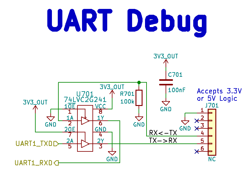
UART pinout
| PIN | Color | Function |
|---|---|---|
| 1 | black | GND |
| 2 | NC | |
| 3 | NC | |
| 4 | green | TX |
| 5 | white | RX |
| 6 | NC |
PIN 1 is the one closest to the volume button while PIN 6 is the one closest to the power button. The pin functions are documented from the perspective of a USB to serial adapter – the devkit receives serial input on pin 4 and transmits serial output on pin 5.
The board can be powered in the usual way with the serial adaptor connected to
your workstation. Depending on your operating system and any other USB devices
you have connected, a serial console should appear as a device file such as
/dev/ttyUSB0. Connect to this using picocom using this device file
instead of the one you would use for a serial connection to the board’s USB C
port:
picocom -b 115200 /dev/ttyUSB0
Use the relevant device file instead of ttyUSB0 as necessary.